I. Introduction
Cimatron E's CNC machining technology has always been a world leader and is considered by the world to be one of the most outstanding CNC programming systems. In addition to providing comprehensive processing applications in the field of machining, such as CNC milling (2.5 to 5 axes), CNC drilling, CNC vehicles, CNC blanking, CNC wire cutting and electrode design, it also provides users with the most advanced Processing technology - Knowledge-based machining, automated NC and intelligent NC based on three techniques of blank residue knowledge. The intelligent NC marks a major technological breakthrough in Cimatron's processing. The intelligent NC mode allows the user to complete NC machining with the click of a button. When the user completes the definition of the process in a particular job each time, simply save the process as a technical template. The tool path is automatically generated the next time the user has to process a part with similar machining process. The knowledge of blank residue allows the user to check the actual blank allowance at any time. The user can also cut the machining path for his own machining strategy and machining purpose. The knowledge of blank residue can be adjusted according to the user's new geometric model, and the tool path can be optimized. Optimization includes removing the air knife, automatically adjusting the feed rate, removing the sharp corners to create a smooth tool motion, or automatically splitting the tool path to avoid interference in the case of collet interference, automatically suggesting new machining tools to machine the raw To the area, etc. Cimatron provides reliable and intuitive trajectory verification and simulation simulation, supporting the comparison analysis of each machining process or part/blank. It displays the current machining results and the remaining amount in the form of color maps. It has visual simulation function of machining. Powerful, allowing users to check the rationality and correctness of the machining process. It can be rotated at any part to observe the machining results. It can also perform up to five-axis simulation verification, quantitative analysis, processing time estimation, etc. Users can also manually Step through the generated tool path. Cinatron also provides users with flexible and convenient track editing. Users can copy existing tool tracks: array copy and rotary copy can also be used to manually and easily modify the generated tool path: delete the selected one. The knife step, the cutting step of the selected selection increases the user's own specified path, and projects the tool path. Cimatron offers high-speed milling technology to meet the demands of increasing processing quality and efficiency, such as NURBS interpolation G code, rounded corners of sharp corners, smooth circular cutting of outer blanks, tool load analysis and automatic optimization. And other tools.
The panel shown in Figure 1 is the main component of the cabinet machine. It is composed of complex curved surfaces. The design of the panel will directly affect the appearance and product quality of the cabinet air conditioner. The Cimatron E5.0 software was used to build the 3D data model of the panel. Based on this, Quick Split and NC programming were carried out, and then the post-processing program was transferred to the CNC machine to complete the actual processing of the panel mold.
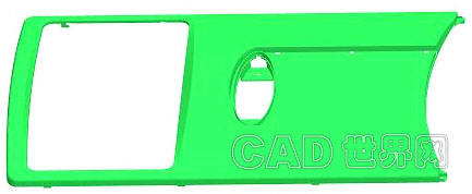
Figure 1 3D model of the cabinet panel
Cabinet panel moulds are an important part of the production of high quality cabinet air conditioners. Due to the appearance conditions and assembly performance of the cabinet panel, strict requirements are imposed on the mold material, intrinsic quality and dimensional accuracy, and the manufacturing is very difficult. On the basis of fully absorbing the essence of Japanese air conditioner mold structure design, our company has developed professional production technology and gradually became an important mold production base in Suzhong area.
The processing steps of the injection mold are generally divided into processes such as roughing, semi-finishing, and finishing. According to the shape and processing characteristics of the mold core of the cabinet, the precision of the surface of the secondary machining is very high. The positioning reference is the lower plane of the base. In order to reduce the number of clamping times and shorten the working hours, the secondary machining needs to be all in the CNC milling machine. Or on a CNC machining center. In CNC machining, in order to minimize auxiliary work hours, special attention must be paid to the use of clamps to ensure rapid positioning and clamping of the machined parts. In the processing, the number of workpiece clamping should be minimized. In one clamping, each process step should be completed as much as possible. For this reason, the positioning method that facilitates the processing of each surface should be considered. With the lower plane of the core as the positioning reference, the processing of other curved surfaces can be easily performed.
Third, CNC machining
Cimatron E5.0 software has powerful processing capabilities, and can also read data from other software such as UG, Pro/ENGINEER. Automatic intelligent programming of CNC machining with CimatronNC module, the steps are as follows:
(1) According to the characteristics of the model, formulate the processing technology;
(2) Perform each step of programming, determine the machining method and parameters such as tool, feed speed, and tool pitch, generate a tool path, and perform a simulation check of the tool path;
(3) generate an NC program;
(4) Transfer the NC program to the corresponding CNC machine tool using CNC transmission software;
(5) After processing the blanks, tools and fixtures, they are processed on the CNC machine.
The following is a brief description of the CNC milling process by taking the fixed core of the mold as an example:
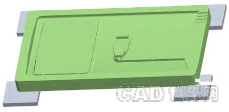
Figure 2 Panel injection molding core (including four square pressure plates)
1. Overall roughing (WCUT)
Using D63 (R8) corn milling cutter, using 3D volumetric spiral machining (Volume Milling - Sipral Cut - 3D), safety plane (CLEARANCE PLANE) is 150mm, helix angle (Ramp Angle) is 5°, processing maximum height ( Z-top) is 90mm, the lowest machining height (Z-bottom) is 40mm, the cut depth is 0.75 mm, the step step is 30 mm, and the Part Surface Offset is 0.5. Mm, Part Surface Toleranc is 0.1mm, Milling Direction is Climb Milling, Cut Direction is Inside Out, part is Open Part is NO, Spindle Speed ​​(SPINDLE_SPEED) At 1000 r/min, the feed rate (CUT_FEED) is 1200 mm/min. Using the Exetute function, the machining tool path is shown in Figure 3. At the same time, the simulation and overcut inspection are performed on the machining. The shape of the entire fixed core is milled out to meet the requirements of the process. Then, post processing (Post) is performed, and the program is automatically generated and sent to the CNC machining center for CNC machining.
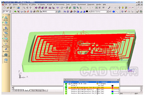
Figure 3 roughing overall shape
Semi-finishing uses D24 (R6) coated insert milling cutter, using Surface Milling (Blay Milling, By Layers) processing, safety plane (CLEARANCE PLANE) is 150mm, processing maximum height (Z-top) is 90mm, The minimum machining height (Z-bottom) is 40mm, the depth of the Down Step is 0.45 mm, the Part Surface Offset is 0.4 mm, the Part Accuracy (Part Surface Toleranc) is 0.1 mm, and the milling direction (Milling) Direction) is Climb Milling, the Cut Direction is Inside Out, the part is Open Part is NO, the spindle speed (SPINDLE_SPEED) is 1300r/min, and the feed speed (CUT_FEED) is 1000mm/min. Using the Exetute function, the machining tool path is shown in Figure 4. At the same time, the simulation and overcut inspection are performed on the machining. The wall allowance of the entire fixed core is removed most of the time, ready for ball processing, in line with the process requirements. Then, post processing (Post) is performed, and the program is automatically generated and sent to the CNC machining center for CNC machining.
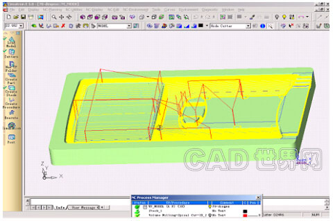
Figure 4 Area roughing
3. Semi-finishing (SRFPKT)
Using D16 (R8) ball end milling cutter, using Surface Milling (Parallel Cut) processing method, the safety plane (CLEARANCE PLANE) is 150mm, the processing maximum height (Z-top) is 90mm, the minimum height of processing (Z-bottom) is 40mm, the step (Side Step) is 0.8 mm, the Part Surface Offset is 0.25 mm, the machining accuracy (Part Surface Toleranc) is 0.05 mm, and the milling direction (Cutter Direction) is Bidir. The cutting angle is 45°, the Direction is Both: Up & Down, the spindle speed (SPINDLE_SPEED) is 1500r/min, and the feed speed (CUT_FEED) is 900mm/min. Using the Exetute function, the machining tool path is shown in Figure 5. At the same time, the simulation and overcut inspection are performed on the machining. The margin of the entire fixed core is removed most of the time, ready for D10 (R5) ball cutter processing, in line with the process requirements. Then, post processing (Post) is performed, and the program is automatically generated and sent to the CNC machining center for CNC machining.

Figure 5 Semi-finished parting surface
4. Finishing (SRFPKT)
Use D10 (R5) ball end milling cutter, using Surface Milling (Parallel Cut) processing method, safety plane (CLEARANCE PLANE) is 150mm, processing maximum height (Z-top) is 90mm, processing minimum height (Z-bottom) is 40mm, the step (Side Step) is 0.2mm, the Part Surface Offset is 0mm, the machining accuracy (Part Surface Toleranc) is 0.01mm, and the milling direction (Cutter Direction) is Bidir. The cutting angle is 135°, the Direction is Both: Up & Down, the spindle speed (SPINDLE_SPEED) is 1800 r/min, and the feed speed (CUT_FEED) is 800 mm/min. Using the Exetute function, the machining tool path is shown in Figure 6. At the same time, the simulation and overcut inspection are performed on the machining. Most of the entire range of fixed cores is ground in place to meet process requirements. Then, post processing (Post) is performed, and the program is automatically generated and sent to the CNC machining center for CNC machining.

Figure 6 Finishing parting surface
5. Finishing 2 (WCUT FINISH)
Semi-finishing uses D20 (R0.8) end milling cutter, using Surface Milling (Blay Milling, By Layers) processing method, safety plane (CLEARANCE PLANE) is 150mm, processing maximum height (Z-top) is 90mm, processing The minimum height (Z-bottom) is 40mm, the depth of the Down Step is 0.45 mm, the Part Surface Offset is 0 mm, the Part Surface Toleranc is 0.01 mm, and the milling direction is Milling Direction. For Mixed Milling, the Cut Direction is Inside Out, whether the part is Open Part is NO, the spindle speed (SPINDLE_SPEED) is 1400r/min, and the feed speed (CUT_FEED) is 1000mm/min. Using the Exetute function, the machining tool path is shown in Figure 7. At the same time, the simulation and overcut inspection are performed on the machining. The wall root balance of the entire fixed core is removed to meet the requirements of the process. Then, post processing (Post) is performed, and the program is automatically generated and sent to the CNC machining center for CNC machining.
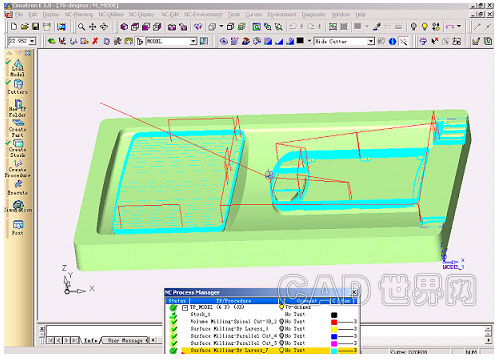
Figure 7 clear angle processing
Fourth, the conclusion
In the processing of the cabinet panel mold, Cimatron's CNC machining technology is adopted, which greatly reduces the error caused by manual design and common equipment processing, and greatly reduces the workload and labor intensity of milling, electric machining, fitter and polishing. The processing efficiency of the mold is improved, the manufacturing cycle of the mold is shortened, the quality of the mold is also improved, and the non-graph processing can be realized, which brings good economic benefits to the enterprise.
Nozzle 6,Multipurpose Jet Nozzle,Rotating Water Jet Nozzle,High Pressure Jet Nozzle
Foshan Hairan Machinery And equipment Co.,LTD , https://www.hairannozzle.com