Process planning is an important part of CNC turning programming. Reasonable planning can effectively improve production efficiency and improve the surface quality of parts. At present, the CNC turning technology planning method for conventional parts has been researched more and more mature, and the corresponding CAM software system has been developed, which provides a powerful tool for NC automatic programming.
However, there is a type of part in turning programming, which is characterized by a complicated cross-sectional profile and different daily blank sizes. This is due to the relatively backward mechanical processing equipment in China and the low precision of rolled blanks. At this time, it is usually programmed according to the maximum blank size, and as a result, an empty cut occurs, and the processing efficiency is lowered. The goal of CNC turning process planning is to pursue single-piece working hours - the shortest (high productivity) or the lowest in machining, and the boundary constraints are no geometric interference and process interference.
Therefore, in the numerical control system with the cutting force detection function, for the numerical control machining of the workpiece with large blank manufacturing error, the cutting force sensor can be used to measure the machining allowance of the blank on-line, and the cutting of different parts of the wheel can be determined according to the machining allowance. Process parameters (cutting thickness, number of passes, etc.), so that different cutting methods can be used for different blank machining, thus saving machining time. This paper intends to take the numerical control turning of train wheels as an example to describe the principle, measurement method and tool path generation method of machining allowance during turning machining of large-difference rotary parts, and to discuss the method of determining feed rate and cutting speed.
1 Blank machining allowance online measurement
Figure 1 is a half-sectional view of a certain type of train wheel. Since the blank is made by hot rolling, the blank size is not uniform, so the machining allowance is not uniform. The number of passes and the number of passes can be determined by online measurement of blank machining allowance. The depth of cut of the knife.

1.1 Principle of measurement
On-line measurement of machining allowance requires the use of the cutting force detection function of the numerical control system. The force detection system is mounted on the tool holder. The core is a load cell that converts the force signal into a voltage signal and transmits it to the CNC through a serial communication protocol. A threshold value (usually set to the yield limit value σs of the wheel material chromium-manganese steel) can be preset in the sensor. When the tool comes into contact with the workpiece and starts cutting, the cutting force suddenly increases. When the cutting force reaches the set threshold value, the CNC will automatically end the cutting of the current measuring block and record the X and Z coordinate values ​​of the current position of the tool. After calculation, the remaining amount of a certain part is stored in the numerical control system. From the appearance, the tool retracts as soon as it touches the workpiece, ie only one knife is measured at one measuring point.
1.2 Method of measurement
According to the principle of machining allowance measurement, the tool cuts along the normal direction of the workpiece ICI during measurement. Figure 2 is an in-line measurement of the machining allowance. In the figure, the point A(x, y) is the planned measurement point, and the tool radius is R. When the cutting is performed, the tool cuts in the normal direction of the workpiece table ICI, and the unit method vector of the cutting allowance of T in the figure can be not calculated. The direction is opposite to the direction of the measured segment vector EA in the figure. Let θ be the angle between the infeed direction and the horizontal line, then n=(cos, sinθ).
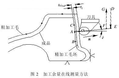
When the tool tip is in contact with the workpiece, the tool center X-direction radius coordinate is R601, then the distance between the point A on the finishing contour and the tool core O is AO=(R601-X)/cosθ
The total cutting allowance ttotal = A0- R = (R601-x ) / cosθ -R, and the finishing allowance is t, the rough machining allowance can be calculated from the total allowance t = ttotal – tr = (R601- x) / cos θ - R-tr.
It is known that the machining allowance is ttotal, the infeed path is D→E→0, and the retraction path is O→F→G. Let the maximum depth of cut be tmax, then the number of roughing cycles N is

The symbol "[]" in the formula is not rounded up. The actual cutting depth of the knife is treal, = t / N. The finished contour is translated by the distance from the normal to the tr distance, and then translated N times. When the translation distance is tral, the tool motion track can be obtained.
Next page
Medical Shoe Covers,Disposable Overshoes,Hospital Shoe Covers,Anti Slip Shoe Covers
Ningbo Autrends Prevention Products Co., Ltd , https://www.autrendsafety.com