1 Scope
This standard applies to photovoltaic (PV) power generation systems interconnected to the grid, which operate in parallel with the grid and use static (semiconductor) non-islanding inverters that convert DC to AC. This standard describes recommendations for systems rated at or below 10kVA, such as single-phase or three-phase systems for stand-alone residences. This standard applies to interconnections with low-voltage power distribution systems.
The purpose of this standard is to specify the interconnection requirements of photovoltaic systems and grid power distribution systems.
Note 1: Inverter type identification shall comply with the specific provisions of this standard should be considered to install, without any further inspection.
This standard does not address the issue of protection mechanisms for electromagnetic compatibility or islanding.
NOTE 2 Interface requirements may vary when there is an energy storage system or when the grid provides control signals to the PV system.
2 normative references
The clauses contained in the following standards constitute the provisions of this standard by reference in this standard. For dated references, all subsequent amendments (not including errata content) or revisions do not apply to this standard, but the parties to the agreement are encouraged to study whether the latest versions of these documents can be used. For undated references, the latest version is applicable to this standard.
GB/T 18479-2001 General description and guidance of surface photovoltaic (PV) power generation systems (idt IEC 61277:1995)
IEC 60364-7-712:2002 Electrical installations of buildings - Part 7-712: Requirements for special installations or locations - Photovoltaic (PV) power generation systems
IEC 61000-3-3:1994 Electromagnetic compatibility (EMC) Part 3-3: Limits Values ​​for voltage changes, voltage fluctuations and flicker in public low-voltage supply systems for rated current per phase (16A, and not Conditionally connected devices.
IEC 61000-3-5:1994 Electromagnetic compatibility (EMC). Part 3-5: Limit values ​​for voltage fluctuations and flicker in low-voltage supply systems for equipment with rated current >16A per phase
IEC 61836:1997 Solar photovoltaic energy system terms and symbols
3 Terms and Definitions
This standard gives the following terms and definitions.
3.1
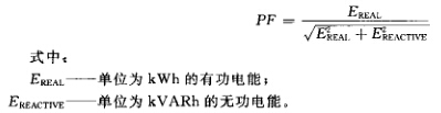
Power factor
The power factor (PF) is calculated by dividing the active energy (kWh) over a period of time by the square root of the sum of the squares of the active and reactive energy (kVARh).
The power factor (PF) formula for a period of time is:
3.2
Square array field
A collection of all solar cell arrays within a power generation system (see GB/T 18479-2001).
3.3
DC interface direct current(DC)interface
The connection between the field of squares and the input terminal of the inverter/power regulation system.
3.4
Power utility
In general, it refers to the agency responsible for the installation, operation and maintenance of the power supply and low voltage distribution system (see GB/T 18479-2001).
3.5
Safe disconnect control and supervisory brake subsystem safety disconnect control and monitoring subsystem
Monitor the status of the utility grid and perform a cut-off of the inverter AC output subsystem.
3.6
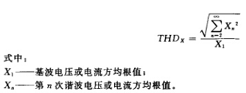
Total harmonic distortion
The distortion rate is defined as:
3.7
Photovoltaic system photovoltaic system
PV system
There is a common point of connection, including all inverters (single or multiple units), associated balance system components (BOS) and the photovoltaic system of the matrix, also known as photovoltaic power plants in IEC 61836:1997.
3.8
Inverter
Static Power Converter (SPC) (see Note 1)
Devices that convert DC to AC. A device that converts direct current from a square field into alternating current. The device converts electrical energy into one or more forms of electrical energy for use in subsequent grids.
Note 1: Static power converters with control, protection and filtering functions for the interface between the power supply and the grid. Sometimes referred to as a power regulation subsystem, a power conversion system, a static converter, or a power conditioning unit.
NOTE 2 Due to its integrated nature, the complete disconnection of the inverter from the grid is only required at the time of repair or maintenance. At all other times, the control circuit maintains the connection to the grid to monitor the grid status, whether or not the inverter is delivering photovoltaic energy to the grid. The phrase “stop sending power to grid lines†is commonly used in this standard. It should be recognized that in the event of a trip, such as an overvoltage trip, the inverter will not be completely disconnected from the grid. Inverter maintenance can be completely disconnected from the grid through a grid AC-break switch.
3.8.1
Non-islanding inverter
The inverters that can send power to the power distribution system can be stopped when the voltage and/or frequency exceed the normal operating range.
Note: See IEC61836:1997.
3.9
Grid interface utility interface
The interconnection between the photovoltaic system and the grid distribution system, the common connection point.
4 Grid compatibility
The quality of the photovoltaic system to provide power to the local AC load and to send power to the grid should be controlled, meet practical requirements in terms of voltage, flicker, frequency, harmonics and power factor and meet the standards. Deviating from the standard over-limit condition may require the PV system to detect this deviation and de-couple it from the grid.
Unless otherwise required, all measurements of power quality parameters (voltage, flicker, frequency, harmonics, power factor) must be made at the grid interface/common junction.
Note: Phase current balance is as much as possible in multiphase systems.
4.1 Voltage, Current, and Frequency
The AC voltage, current and frequency of the PV system should be matched to the grid system.
4.2 normal voltage working range
Grid-connected PV systems generally do not regulate voltage, but instead inject current into the grid. Therefore, the protection function is considered when selecting the voltage operating range of the PV inverter, that is, reacting to the exceeding of the grid operating condition without considering the voltage regulation function.
4.3 Flicker
The voltage flicker caused by PV system operation should not exceed the limits specified in the relevant sections of IEC 61000-3-3 (less than 16A systems) or IEC 61000-3-5 (16A and above systems).
4.4 DC injection component
In any operating state, the DC current injected from the PV system to the grid AC interface should not exceed 1% of the inverter output current.
4.5 Normal Frequency Operating Range
The photovoltaic system should run synchronously with the grid, and frequency deviation limits are given in 5.2.2.
4.6 Harmonic and Waveform Variations
Low levels of current and voltage harmonics are desirable; higher levels of harmonics increase the potential for harmful effects on connected equipment.
The permissible levels of harmonic voltages and currents depend on the characteristics of the distribution system, the mode of operation, the connected load/instrument, and the actual current regulations of the power supply organization.
The output of the PV system should have a low level of current distortion to ensure that it does not adversely affect other equipment connected to the grid.
The total harmonic current should be less than 5% of the nominal inverter output. Each harmonic should be limited to the percentages listed in Table 1.
The even harmonic limit in this range should be less than 25% of the lower odd harmonics.

4.7 Power Factor
When the output is greater than 50% of the rated output power of the inverter, the lagging power factor of the photovoltaic system should be greater than 0.9.
Note 1: Specially designed systems providing reactive power compensation can operate beyond this limit, with the permission of the power supply authority.
Note 2: Most inverter power factors designed for grid-tied operation are close to 1.
5 personal safety and equipment protection
This clause gives the content and considerations for the safe and correct operation of grid-connected PV systems.
Note 1: The protection function can be provided by the system's internal or external devices.
Note 2: IEC 60364-5-55, national standards or local regulations may be used.
5.1 Loss of power network
In order to prevent the islanding effect, the grid-connected PV system should stop sending power to the blackout distribution line within a certain time limit, regardless of the load or other generators it carries.
There may be multiple reasons for a power outage on the distribution network. For example, the substation breaker trips due to a fault condition, or the power distribution circuit is opened during maintenance.
If the inverter (single or multiple units) has a DC safety extra-low voltage SELV input and the total power is less than 1 kW, no mechanical disconnect (relay) is required.
5.2 Over/under voltage and over/under frequency
Abnormal conditions may appear on the grid, requiring the photovoltaic system connected to it to respond. This response ensures the personal safety of the maintenance staff and the general public of the power supply organization, while avoiding damage to connected equipment, including photovoltaic systems. The associated abnormal grid condition is a complete de-coupling of the voltage and frequency deviations above or below the values ​​specified in this clause and the potential islanding effect of the distribution power supply.
5.2.1 Over / Undervoltage
When the interface voltage deviates from the state specified in Table 2, the photovoltaic system shall stop sending power to the power distribution system. This requirement applies to any phase in a multiphase system.
The system voltage referred to in this standard refers to the local nominal voltage.
The system should be able to detect abnormal voltage and react. The following conditions should be met: The voltage value is a square root and measured at the grid interface.

5.2.2 Over/under frequency
When the grid frequency deviates from a specific state, the photovoltaic system should stop sending power to the grid line. If the frequency returns to normal grid continuous operation within the specified opening time, there is no need to stop the power transmission.
When the grid frequency exceeds the range of ±0.5Hz, the system shall stop sending power to the grid line within 0.2s. The purpose of the allowable range and delay is to avoid excessive tripping due to short-term disturbances.
5.3 Island Effect Protection
The photovoltaic system must stop sending power to the grid line within 2s of the grid voltage loss.
The issue of non-island inverters is addressed by other standards being developed.
5.4 Grid Recovery
After the photovoltaic system stops power transmission due to the overrun state, the photovoltaic system is not allowed to transmit power to the grid circuit for a period of time after the grid operating voltage and frequency recovers to a specific range. The delay time of the power transmission is in the range of 20s to 5min.
Note: The power delay depends on local conditions.
5.5 Ground
Grid interface equipment should be grounded/wired to the protective conductor in accordance with IEC 60364-7-712.
5.6 Short Circuit Protection
Photovoltaic systems should have short circuit protection according to IEC 60364-7-712.
5.7 Isolation and Switching
IEC 60364-7-712 isolation and switching methods should be provided.
Energy Conservation Transformation For 300Mw Coupling
Engery Conservation Transformation For 300Mw Coupling
Vertical Turbine Pump,Boiler Feed Pumps,Feed Pump,Viscous Coupling Modification
Shenyang pump products sales co., LTD , https://www.syipsc.com