With the popularization of 3D CAD software , many students with only 2D CAD design experience hope to have a "shortcut" to master 3D design. Today, Xiaobian chooses Zhongwang 3D, which is suitable for entry 3D CAD design software , used in September. Case teaching software , share with you how to use the most commonly used 3D CAD function to quickly draw ZIPPO lighters, I believe that with learning to draw once, you can understand the 3D CAD design ideas to help you get rid of the traditional thinking of the original 2D design. The 3D official forum of Zhongwang 3D (or Baidu search 3D zippo) also provides free download of 3D CAD model of Zippo lighter.

1. Insert sketch 1 on the XY plane and draw the graph as shown in Figure 1. Exit the sketch, stretch the sketch 1, stretch the length to 200, click on the rounded corner, and make a rounded corner with a radius of 6, as shown in Figure 2; Insert sketch 2 on the XZ plane, draw the graph shown in Figure 3, click Stretch--Decrement, the outline is Sketch 2, as shown in Figure 4, and the edge is rounded with a radius of 6, as shown in Figure 5.
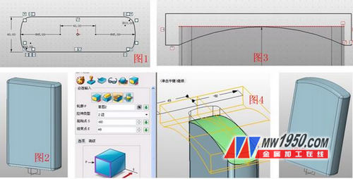
2, click on the shell, select the shape, the thickness is -2, as shown in Figure 6; insert the XY datum, the offset distance is 120, click on the split, select the shape, the split surface is the XY datum, and divide the shape into two parts, such as Figure 7; Click Move - Dynamic Move, as shown in Figure 8, the upper portion is moved to the position shown in Figure 9 by the movement of the angle and distance.

3. Insert sketch 3 on the XZ plane, draw a circle with a radius of 3 at the position shown in Figure 10, and stretch the sketch into a cylinder. The parameters are shown in Figure 11. Pay attention to the "base" option in the extrusion; hide the shell, Insert the sketch 4 on the XY plane, draw the four rectangles shown in Figure 12, click the stretch--minus operation, and stretch the sketch 4 to show the hidden part. The effect is shown in Figure 13.

4. Stretch an entity with the inner edge of the shell as the contour. The parameters are shown in Figure 14. Note that the draft angle is -0.5, so there will be tiny gaps between the solid and the shell; click chamfer--asymmetric chamfer, Chamfer the upper edge of the solid, the parameters are shown in Figure 15; insert a sketch on the XZ plane, draw a line segment, as shown in Figure 16, exit the sketch, click the stretch--minus operation, stretch the line segment, pay attention to the offset, offset The choice, as shown in Figure 17; insert a sketch 5 on the XY plane, draw a rectangle, as shown in Figure 18, stretch the sketch 5, the parameters are shown in Figure 19, pay attention to the selection plus operation.
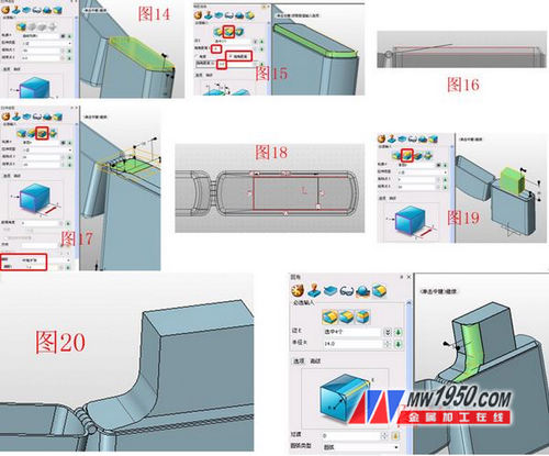
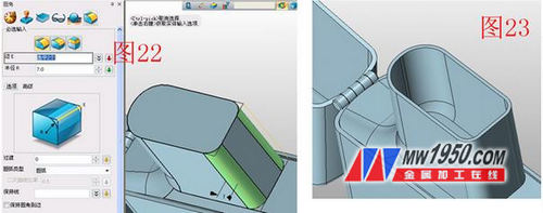
5. The position shown in Figure 20 is rounded with a radius of 15; rounded at the position shown in Figure 21, with a radius of 14, and then the other side; in the position shown in Figure 22, the two sides are inverted. Rounded corners with a radius of 7, after which the shape is shelled to a thickness of -1.5, and the open roof is the top surface, as shown in Figure 23.
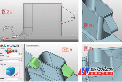
6. Insert the sketch 6 on the XZ plane, draw the graph shown in Figure 24, and stretch the sketch 6 with the stretched addition operation. The stretch type is "symmetric" and the end point is 7, as shown in Figure 25; The position shown in Figure 27 is rounded with a radius of 1, 2, respectively.
7. Insert the sketch 7 on the XY plane, draw the rectangle shown in Figure 28, and the parameters are as shown in the figure; use the subtraction of the stretch to stretch the sketches of the two rectangles respectively, the parameters are as shown in Figure 29, 30; and the sketch 8 is inserted in the XZ plane. Draw the graph shown in Figure 31, stretch the sketch 8, the stretch type is "symmetric", and the end point is 5.5, as shown in Figure 32.

8. Insert sketch 9 on the XZ plane, draw a circle with a radius of 3 at the position shown in Figure 33, and stretch the sketch 9, the extension type is symmetrical, the end point is 8, and the rounded edge is chamfered, the distance 0.5, the side chamfer of the runner, the distance is 1.2, as shown in Figure 34; click the stretch minus operation, the contour is the chamfered edge of the runner, the parameters are as shown in Figure 35, pay attention to the choice of offset type and distance; click on the array - Linear, set the attribute filter to "feature", the base selects the subtracted part of Figure 35, other parameters are shown in Figure 36; insert the sketch 10 on the XZ plane, draw the rectangle shown in Figure 37, click on the stretch minus Stretch the sketch 10, the parameters are shown in Figure 38; click on the array again - circle, and circle the subtracted part, the parameters are shown in Figure 39.

9. Insert sketch 11 on the XY plane and draw a circle with a radius of 8, as shown in Figure 40; click on the stretch plus operation to stretch the sketch 11, the parameters are shown in Figure 41; the bottom edge of the cylinder is rounded, the radius is 1.5, The upper edge of the cylinder is stretched again for the contour, the tensile height is 8, the offset selects the "contraction/expansion" offset to be 1, and the upper edge of the tensile body is chamfered, the distance is 1, as shown in Figure 42; The method of stretching the flint, parameters and effects are shown in Figure 43.

10, XZ plane into the sketch 12, draw 8 circles with a radius of 4, as shown in Figure 44; click on the stretch - the base, stretch the sketch 12, as shown in Figure 45; click on the combination - minus, subtract the middle of the four The cylinder, as shown in Figure 46; click on the move - dynamic movement, adjust the other four cylindrical positions, as shown in Figure 47, again subtracted by the combination subtraction. Finally, you can use the text tool to type the word on the shell of the lighter. The renderings and renderings are as follows.

At this point, the ZIPPO lighter has completed all the 3D CAD modeling process, and the 3D simple operation process can help the users who want to realize the 2D CAD design upgrade. They can familiarize themselves with the 3D design with a lower threshold. Now, 3D is also expected. Provide the latest "hands-on" learning tutorial, which is prepared by the teacher who is familiar with 3D, Proe (NX) and Solidworks, and is more closely related to the 3D CAD learning needs of beginners!
Zhongwang 3D 3D CAD/CAM software
Zhongwang 3D is the preferred brand of 3D CAD/CAM software for military enterprises recommended by the Ministry of Industry and Information Technology. It provides cost-effective 3D CAD/CAM solutions for enterprises, modeling, mold, assembly, reverse engineering, sheet metal, 2-5 axis processing and other functions. The modules are available. Efficient and compatible with other 3D CAD software , easy to learn and use, integrated rich parts library, new learning tutorials and free download of massive quality 3D CAD drawings, so that you can master 3D design and machining programming more easily. Download the latest version now and apply for free 3D CAD/CAM & 3D printing technology training.
Suzhou Newstar Hardware Co.,Ltd is China wrench set supplier and manufacturer located in Jiangsu, nearby Shanghai. We could offer you various wrench set, spanner set, box wrench, spanner wrench set, etc. We offered that you can trust. We are also very strong at customized services, OEM and ODM, with customer logo and requirements of different types of package, tools material, tool size and other needs on Hand Tool, and hand Tool Kit. Looking forward to work with you together.
Wrench Set,Spanner Set,Box Wrench,Spanner Wrench Set
SUZHOU NEWSTAR HARDWARE CO.,LTD. , https://www.hardwarenewstar.com